
Thursday, March 13, 2014
Wednesday, March 5, 2014
driving a phone keypad matrix
I got given this old phone to take apart:

 and decided to make it work as a numpad.
I had to solder the wires from the ribbon cable onto headers so that I could plug it into my breadboard.. that's really difficult to do - I think you're supposed to have a PCB between the plastic of the headers and the metal you're working with. I ended up soldering 11/12 pins successfully, luckily I didn't need the last one.
 on the very first pin the head and tension managed to pull the pin up a bit, this happened even worse on the final pin.
For the first circuit I made a wrong assumption about the internals, plugged it in and tried it and it didn't work:

So I traced out the schematic of the keypad and the way it function is that when you press key on row r and column c it completes a circuit between pin Rr and Cc.

I spent a while trying to figure out how to drive this circuit without having to pull the header out of the breadboard:
I came up with the plan that I could scan through the columns by firing an output on them one by one, and check if that came though any of the row pins as inputs... but thinking back to the http://www.ruggedcircuits.com/10-ways-to-destroy-an-arduino I was aware of the danger of shorting a high output to a low output (if you held down two keys on the same row but different columns).
There are actually two solutions to this, I think. In the end I did both even though - I think - only one is necessary. First of all (and this works without pulling the thing out the breadboard) you can just set your pins to be inputs pins when they're not outputting HIGH, that means you'll never have a LOW output short to a HIGH output! N.B. when the teensy starts up its pins are all configured to be inputs, since that is safer. You can set the ones you're not using to be low outputs for reduced energy consumption. The other solution is that since LOW outputs can sink a few milliamps, just use resistors to limit the current.
In fact I went with that and coded it up and tried it and.... without pressing anything it entered "1" and then did absolutely nothing. I had to put debugging info in and it turned out all my inputs were coming in as 1's all the time. So I added pull-down resistors and it all worked nicely! I actually reasoned that I did not need pull-down resistors earlier, but I was wrong and don't understand why.0
Here's the schematic I ended up with

a photo of the working build!

and the code which is based on PJRC usb_keyboard_debug example:
I had to solder the wires from the ribbon cable onto headers so that I could plug it into my breadboard.. that's really difficult to do - I think you're supposed to have a PCB between the plastic of the headers and the metal you're working with. I ended up soldering 11/12 pins successfully, luckily I didn't need the last one.
For the first circuit I made a wrong assumption about the internals, plugged it in and tried it and it didn't work:
So I traced out the schematic of the keypad and the way it function is that when you press key on row r and column c it completes a circuit between pin Rr and Cc.
I spent a while trying to figure out how to drive this circuit without having to pull the header out of the breadboard:
I came up with the plan that I could scan through the columns by firing an output on them one by one, and check if that came though any of the row pins as inputs... but thinking back to the http://www.ruggedcircuits.com/10-ways-to-destroy-an-arduino I was aware of the danger of shorting a high output to a low output (if you held down two keys on the same row but different columns).
There are actually two solutions to this, I think. In the end I did both even though - I think - only one is necessary. First of all (and this works without pulling the thing out the breadboard) you can just set your pins to be inputs pins when they're not outputting HIGH, that means you'll never have a LOW output short to a HIGH output! N.B. when the teensy starts up its pins are all configured to be inputs, since that is safer. You can set the ones you're not using to be low outputs for reduced energy consumption. The other solution is that since LOW outputs can sink a few milliamps, just use resistors to limit the current.
In fact I went with that and coded it up and tried it and.... without pressing anything it entered "1" and then did absolutely nothing. I had to put debugging info in and it turned out all my inputs were coming in as 1's all the time. So I added pull-down resistors and it all worked nicely! I actually reasoned that I did not need pull-down resistors earlier, but I was wrong and don't understand why.0
Here's the schematic I ended up with
a photo of the working build!
and the code which is based on PJRC usb_keyboard_debug example:
#include <avr/io.h>
#include <avr/pgmspace.h>
#include <util/delay.h>
#include "usb_keyboard_debug.h"

#define LED_ON        (PORTD |= (1<<6))
#define LED_OFF        (PORTD &= ~(1<<6))
#define LED_CONFIG    (DDRD |= (1<<6))

#define CPU_PRESCALE(n)    (CLKPR = 0x80, CLKPR = (n))

#define DIT 10
#define PRESS(r,c) (pressed_tmp = 1, (pressed?0:(pressed = 1, usb_keyboard_press(number_keys[c+4*r], 0))))

uint8_t number_keys[]=
  {KEY_1,KEY_2,KEY_3,KEY_MINUS,
   KEY_4,KEY_5,KEY_6,KEYPAD_PLUS,
   KEY_7,KEY_8,KEY_9,KEY_TILDE,
   KEYPAD_ASTERIX,KEY_0,KEY_SLASH,KEY_EQUAL};

int main(void) {
  uint8_t d;
  int pressed;
  int pressed_tmp;

  // set for 16 MHz clock, and make sure the LED is off
  CPU_PRESCALE(0);
  LED_CONFIG;
  LED_OFF;

  // we have the following pinout
  //
  // C7, C6, C5, C4, C3, C2, C1, C0
  // [ 10k outputs ] [ inputs     ]
  // 10k changd to 470

  // See the "Using I/O Pins" page for details.
  // http://www.pjrc.com/teensy/pins.html
  DDRC = 0; // make everything an input to start with

  // Initialize the USB, and then wait for the host to set configuration.
  // If the Teensy is powered without a PC connected to the USB port,
  // this will wait forever.
  usb_init();
  while (!usb_configured()) /* wait */ ;

  // Wait an extra second for the PC's operating system to load drivers
  // and do whatever it does to actually be ready for input
  _delay_ms(1000);

  pressed = 0;
  while(1) {
    pressed_tmp = 0;

    // col1
    DDRC |= 1<<4; // make this an output
    PORTC |= 1<<4; // enable it
    _delay_ms(DIT);
    d = PINC;
    usb_debug_putchar((d&(1<<0))?'#':'_');
    usb_debug_putchar((d&(1<<1))?'#':'_');
    usb_debug_putchar((d&(1<<2))?'#':'_');
    usb_debug_putchar((d&(1<<3))?'#':'_');
    usb_debug_putchar('\n');
    if(d&(1<<0)) { PRESS(0,0); } // row1
    if(d&(1<<1)) { PRESS(0,1); } // row2
    if(d&(1<<2)) { PRESS(0,2); } // row3
    if(d&(1<<3)) { PRESS(0,3); } // row4
    PORTD &= ~(1<<4); // disable it
    DDRC &= ~(1<<4); // make it an input again

    // col2
    DDRC |= 1<<5; // make this an output
    PORTC |= 1<<5; // enable it
    _delay_ms(DIT);
    d = PINC;
    usb_debug_putchar((d&(1<<0))?'#':'_');
    usb_debug_putchar((d&(1<<1))?'#':'_');
    usb_debug_putchar((d&(1<<2))?'#':'_');
    usb_debug_putchar((d&(1<<3))?'#':'_');
    usb_debug_putchar('\n');
    if(d&(1<<0)) { PRESS(1,0); } // row1
    if(d&(1<<1)) { PRESS(1,1); } // row2
    if(d&(1<<2)) { PRESS(1,2); } // row3
    if(d&(1<<3)) { PRESS(1,3); } // row4
    PORTD &= ~(1<<5); // disable it
    DDRC &= ~(1<<5); // make it an input again

    // col3
    DDRC |= 1<<6; // make this an output
    PORTC |= 1<<6; // enable it
    _delay_ms(DIT);
    d = PINC;
    usb_debug_putchar((d&(1<<0))?'#':'_');
    usb_debug_putchar((d&(1<<1))?'#':'_');
    usb_debug_putchar((d&(1<<2))?'#':'_');
    usb_debug_putchar((d&(1<<3))?'#':'_');
    usb_debug_putchar('\n');
    if(d&(1<<0)) { PRESS(2,0); } // row1
    if(d&(1<<1)) { PRESS(2,1); } // row2
    if(d&(1<<2)) { PRESS(2,2); } // row3
    if(d&(1<<3)) { PRESS(2,3); } // row4
    PORTD &= ~(1<<6); // disable it
    DDRC &= ~(1<<6); // make it an input again

    // col4
    DDRC |= 1<<7; // make this an output
    PORTC |= 1<<7; // enable it
    _delay_ms(DIT);
    d = PINC;
    usb_debug_putchar((d&(1<<0))?'#':'_');
    usb_debug_putchar((d&(1<<1))?'#':'_');
    usb_debug_putchar((d&(1<<2))?'#':'_');
    usb_debug_putchar((d&(1<<3))?'#':'_');
    usb_debug_putchar('\n');
    if(d&(1<<0)) { PRESS(3,0); } // row1
    if(d&(1<<1)) { PRESS(3,1); } // row2
    if(d&(1<<2)) { PRESS(3,2); } // row3
    if(d&(1<<3)) { PRESS(3,3); } // row4
    PORTD &= ~(1<<7); // disable it
    DDRC &= ~(1<<7); // make it an input again

    usb_debug_putchar('\n');
    if(!pressed_tmp) pressed = 0; // nothing was pressed this whole scan
    // so reset and allow a new keypress
  }
}
Tuesday, March 4, 2014
Flip Flop [standalone electronics]

Here's what I just built, it's called a flip-flop and it lets you select which LED is on by pressing the button. The schematic is like this:


The mechanism is that the circuit has two stable states (well if you run the circuit in a perfect simulation it has a third semi-stable state which you can't get in real life, a bit like balancing a coin on its side):

These states are stable because the large current loop flows much easier through 100 ohms + a transistor than 100 ohms + 1k ohms to try to saturate the other transistor.
In state a, when you press the switch s1 it shorts out the current that was trying to saturate the transistor, so that transistor can no longer be active and the large current is redirected through the 1k resistor to saturate the other transistor putting it into state b.
Saturday, March 1, 2014
Using a scalextrics controller with teensy through ADC

So I opened up the part of the scalextrics track which you plug these devices into and it contained this nice PCB:

The way this works is that you have a transformer from the mains which goes from 240V to 15V, and goes into PLG1 - then if you trace out the schematic you can see that this is exactly a four diode full wave rectifier:

I tried measuring the resistance again but this time through the wires on my modified microtrack PCB and I got readings from between 20 and 200 ohms as I squeezed it!
I needed to design a circuit to connect this to the teensy, so I first tried to limit the current (so as not to damage my nice micro) using a 470ohm resistor then into the variable resistor and to the ADC pin but I thought I should also have a plug into the ground for some reason?


I modified my earlier usb_serial code using the nice example code for ADC from pjrc to get a program that streamed the scalextric reading to my computer through serial:
#include <avr/io.h>
#include <avr/interrupt.h>
#include <avr/pgmspace.h>
#include <util/delay.h>

#include "usb_serial.h"
#include "analog.h"

#define CPU_PRESCALE(n) (CLKPR = 0x80, CLKPR = (n))

// Send a string to the USB serial port.  The string must be in
// flash memory, using PSTR
//
void send_str(const char *s)
{
    char c;
    while (1) {
        c = pgm_read_byte(s++);
        if (!c) break;
        usb_serial_putchar(c);
    }
}

int main(void) {
  int16_t a;
  int i;

  CPU_PRESCALE(0);

  // USB initialization routine taken from example.c
  usb_init();
  while (!usb_configured());
  _delay_ms(1000);
  // wait for the user to run their terminal emulator program
  // which sets DTR to indicate it is ready to receive.
  while (!(usb_serial_get_control() & USB_SERIAL_DTR)) /* wait */ ;
  // discard anything that was received prior.  Sometimes the
        // operating system or other software will send a modem
        // "AT command", which can still be buffered.

  usb_serial_putchar('s');
  usb_serial_putchar('c');
  usb_serial_putchar('a');
  usb_serial_putchar('l');
  usb_serial_putchar('e');
  usb_serial_putchar('x');
  usb_serial_putchar('t');
  usb_serial_putchar('r');
  usb_serial_putchar('i');
  usb_serial_putchar('c');
  usb_serial_putchar('\r');
  usb_serial_putchar('\n');
  while(1) {
    a = adc_read(0);
    usb_serial_putchar(hex[((a>>12)&0xF)]);
    usb_serial_putchar(hex[((a>>8)&0xF)]);
    usb_serial_putchar(hex[((a>>4)&0xF)]);
    usb_serial_putchar(hex[((a>>0)&0xF)]);

    usb_serial_putchar('\n');

    _delay_ms(70);
  }
}
Once I had calibrated the values I made it print lines of #'s so that I could draw waves by squeezing it:

ADB working!
Since ADB had already been implemented and worked on very hard by other people I decided to use my connector and just try out blarggs code. When I first tried it was sort of working but it limited my typing speed horribly.. so I tried the other. It had the same problem but when I started it up it printed 8888888888 and the 7 and 8 keys were broken, so I properly ripped them as you can see:
 Then the ADB code works perfectly! I typed for the rest of the day on my ancient apple keyboard. I still have the other two keycaps so it might be possible to buy new keyswitches and repair it (?).
 I have a wacom tablet which would be nice to use but it's so small, I'm not sure if I'll bother implementing drivers for it.
Saturday, February 22, 2014
Logic Analyzer - part2

Here is a new logic capture of exactly the same circuit using my new code that I just wrote. It's interrupt timer based and uses the usb_serial library to stream the data back to the computer at 62.5 kHz. That figure comes from the 16 MHz clock triggering a timer overflow every 256 clocks.
This capture came out absolutely perfect, compare it to the previous one - it's beautiful! show's how misleading a capture can be without enough samples. I also put an error detector into the code which should light up the LED on the board if a sample is missed from the usb_serial communication taking too much time - this should tell me if try running the capture with too many samples per second although I may need more error detection.
The first thing I did was run the usb_serial tx benchmark and then wrote my own code to send data - at the start it was getting 1/3'd the speed but that's because I was sending one character at a time rather than sending a reasonable sized buffers.
#include <avr/io.h>
#include <avr/interrupt.h>
#include <avr/pgmspace.h>
#include <util/delay.h>
#include <stdint.h>

#include "usb_serial.h"

#define LED_CONFIG    (DDRD |= (1<<6))
#define LED_ON        (PORTD &= ~(1<<6))
#define LED_OFF        (PORTD |= (1<<6))

#define CPU_PRESCALE(n) (CLKPR = 0x80, CLKPR = (n))

volatile int n;
uint8_t buf[64];

int main(void) {
  CPU_PRESCALE(0);

  LED_CONFIG;
  LED_OFF;

  // set the F port to act as input pins without a pullup resistor
  PORTF = 0;
  DDRF = 0;

  /* ******************* */
  // at 16 MHz the fastest timer will overflow at 16/256 = 62.5 kHz
  // Setup the registers for Normal mode:

  // TCCR0A is [COMOA1,0,COM0B1,0,-,-,WGM01,0]
  // compare output match bits are all zero
  // waveform generation mode is zero to select Normal mode
  TCCR0A = 0;

  // TCCR0B is [FOC0A,B,-,-,WGM02,CS02,1,0]
  // Force output compare is zero
  // Clock select is 0,0,1 for the non-prescaled clock
  TCCR0B = 1;

  // Timer/counter interrupt mask register
  // the TOIE0 bit enables interrupts when the timer overflows
  TIMSK0 = (1<<TOIE0);

  // Timer counter register is reset to zero
  TCNT0 = 0;

  /* ******************* */

  buf[0] = 0xC0;
  buf[1] = 0xB0;
  n = 2;

  // USB initialization routine taken from example.c
  usb_init();
  while (!usb_configured());
  _delay_ms(1000);
  // wait for the user to run their terminal emulator program
  // which sets DTR to indicate it is ready to receive.
  while (!(usb_serial_get_control() & USB_SERIAL_DTR)) /* wait */ ;
  // discard anything that was received prior.  Sometimes the
        // operating system or other software will send a modem
        // "AT command", which can still be buffered.

  // enable global interrupts
  sei();

  while(1) {
    if(n == 64) {
      usb_serial_write(buf, 64);
      usb_serial_flush_output();
      n = 2;
    }
  }
}

ISR(TIMER0_OVF_vect) {
  if(n <= 63) {
    buf[n] = PINF;
    n++;
  }
  else {
    // looks like the main loop didn't manage to write in time and we missed a sample
    LED_ON;
  }
}
I used the following script on my computer to stream the data from the virtual serial device into a file (withour having to wait for line buffering):
#include <stdio.h>
#include <stdlib.h>
#include <string.h>
#include <sys/types.h>
#include <sys/stat.h>
#include <fcntl.h>
#include <unistd.h>
#include <termios.h>

#define BLOCKSIZE 1024

int main(int argc, char **argv)
{
    char buf[BLOCKSIZE];
    int port;
    long n, m, sum=0, dotcount=0;
    struct termios settings;
    FILE *dump;

    if (argc < 3) {
        fprintf(stderr, "Usage:   serial_dump <port> <filename>\n");
        #if #system(linux)
        fprintf(stderr, "Example: serial_dump /dev/ttyACM0 <filename>\n");
        #else
        fprintf(stderr, "Example: serial_dump /dev/cu.usbmodem12341 <filename>\n");
        #endif
        return 1;
    }

    // Open the output file
    dump = fopen(argv[2], "w");
    if(!dump) {
      fprintf(stderr, "Unable to open %s for writing\n", argv[2]);
      return 1;
    }

    // Open the serial port
    port = open(argv[1], O_RDONLY);
    if (port < 0) {
        fprintf(stderr, "Unable to open %s for reading\n", argv[1]);
        return 1;
    }

    // Configure the port
    tcgetattr(port, &settings);
    cfmakeraw(&settings);
    tcsetattr(port, TCSANOW, &settings);

    m = 0;
    while (1) {
      n = read(port, buf+m, sizeof(buf)-m);
      m += n;

      if (n < 1) {
        fprintf(stderr, "error reading from %s\n", argv[1]);
        break;
      }

      if (m == sizeof(buf)) {
        fwrite(buf, sizeof(buf), 1, dump);
        fflush(dump);
        m = 0;
      }
    }

    close(port);

    return 0;
}
and as the packets themselves include a "magic" (this may be considered superstitious and I might remove it in future) to detect if any bytes were lots I used the following to convert the dump into something I could open in sigrok:
#include <stdio.h>

void main(void) {
  int i;
  int b;

  i = 0;
  while((b = getchar()) != EOF) {
    if(i == 0) {
      if(b != 0xC0) {
    fprintf(stderr, "ERR");
    return;
      }
    }
    else if(i == 1) {
      if(b != 0xB0) {
    fprintf(stderr, "ERR!");
    return;
      }
    }
    else {
      putchar(b);
      fflush(stdout);
    }
    i++;
    if(i == 64) {
      i = 0;
    }
  }
  fflush(stdout);
}
Tuesday, February 18, 2014
digitally controlled FM radio kit!
I'm so happy! I given an FM radio kit as a present and I just soldered it all together today and it works!! Here's some pictures


There are two IC's on it, one is just am amplifier and the other is a specially programmed PIC microcontroller which lets you control volume, search for channels and load and save presets! It's a fantastic little device, I'm curious which part does the tuning - I originally thought it had an FM tuner chip but no!
There are two IC's on it, one is just am amplifier and the other is a specially programmed PIC microcontroller which lets you control volume, search for channels and load and save presets! It's a fantastic little device, I'm curious which part does the tuning - I originally thought it had an FM tuner chip but no!
Saturday, February 15, 2014
teensy logic analyzer - first try
I would need to be able to do logic analysis on the ADB data channel if I was going to implement ADB (although I'm intimidated by the difficulty so I may not do this), I also thought that interfacing with a microchip and getting data from it back to the computer is a really good 'next step' in learning to use the microcontroller.
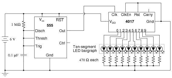
So I built up a circuit which uses a 555 timer to generate a clock pulse at around 13Hz:
and then I used the clock pulse of that to drive my 4017 binary counter - put a couple LEDs down to test it and it worked okay (the counter seemed to skip certain numbers every few cycles.. but I tried moving the LEDs to different output pins of the 4017 and then it looked okay).
I got this circuit working with a 9V battery, then I halved the resistors and got it working again but powered by the teensy (but not having the teensy connected to it in any other way).
Now the datasheet for the decade counter shows the kind of output you get:
 so what I wanted to do what put a connector cable on each pin of port F (say) of the teensy, and then use these as probes to watch the logic levels coming out of the counter microchip. I spent a long time worrying about whether there was a danger of a short-circuit and that I needed to use a resistor to do this safely (or maybe pullups, pulldowns), I'm still not 100% sure what is safe and not but I gather that input pins are "high impedance" having internal resistance around 10k or 1M ohm, you can check the data sheets and see that the voltage output of the counter is within bounds of the acceptable voltage inputs of the micro - that was fine. So having satisfied myself that it was safe I attached some probes and started to write...

I don't know the best way to "stream" data from the teensy into my computer through the USB port - it takes time to output a packet so this severely limits the sampling rate (if I don't want to just fill the RAM up a quick capture running as fast as possible before stopping analysis and uploading it - hopefully wont need to go this route).
On the teensy site there's USB example code:
So here "logic.c" which is the usb example code sped up to sample about 20x faster and instead of outputting ADC inputs it just outputs the valee of the F port (all 8 pins):
so running this went fine, nothing exploded - and I extracted the bytes from the packets, converted to a binary file with
then used the command line sigrok tool to turn it into a sigrok session, loaded it into pulseview and saw this!
next step get it sampling much faster and maybe put in some error detection!
So I built up a circuit which uses a 555 timer to generate a clock pulse at around 13Hz:
 |
| ohmslawcalculator/555_astable |
I got this circuit working with a 9V battery, then I halved the resistors and got it working again but powered by the teensy (but not having the teensy connected to it in any other way).
Now the datasheet for the decade counter shows the kind of output you get:
I don't know the best way to "stream" data from the teensy into my computer through the USB port - it takes time to output a packet so this severely limits the sampling rate (if I don't want to just fill the RAM up a quick capture running as fast as possible before stopping analysis and uploading it - hopefully wont need to go this route).
On the teensy site there's USB example code:
- https://www.pjrc.com/teensy/usb_serial.html
- https://www.pjrc.com/teensy/rawhid.html
- https://www.pjrc.com/teensy/uart.html
So here "logic.c" which is the usb example code sped up to sample about 20x faster and instead of outputting ADC inputs it just outputs the valee of the F port (all 8 pins):
#include <avr/io.h>
#include <avr/pgmspace.h>
#include <avr/interrupt.h>
#include <util/delay.h>
#include "usb_rawhid.h"
#include "analog.h"

#define CPU_PRESCALE(n)    (CLKPR = 0x80, CLKPR = (n))

volatile uint8_t do_output=0;
uint8_t buffer[64];

int main(void)
{
    uint8_t i;
    uint16_t count=0;

    // set for 16 MHz clock
    CPU_PRESCALE(0);

    // set the F port to act as input pins without a pullup resistor
    PORTF = 0;
    DDRF = 0;

    // Initialize the USB, and then wait for the host to set configuration.
    // If the Teensy is powered without a PC connected to the USB port,
    // this will wait forever.
    usb_init();
    while (!usb_configured()) /* wait */ ;

    // Wait an extra second for the PC's operating system to load drivers
    // and do whatever it does to actually be ready for input
    _delay_ms(1000);

        // Configure timer 0 to generate a timer overflow interrupt every
        // 256*1024 clock cycles, or approx 61 Hz when using 16 MHz clock
        TCCR0A = 0x00;
        TCCR0B = 0x05;
        TIMSK0 = (1<<TOIE0);

    while (1) {
        // if time to send output, transmit something interesting
        if (do_output) {
            do_output = 0;
            // send a packet, first 2 bytes 0xABCD
            buffer[0] = 0xAB;
            buffer[1] = 0xCD;
             // put input pin values in the next byte
            buffer[2] = PINF;
            // most of the packet filled with zero
            for (i=3; i<62; i++) {
                buffer[i] = 0;
            }
            // put a count in the last 2 bytes
            buffer[62] = count >> 8;
            buffer[63] = count & 255;
            // send the packet
            usb_rawhid_send(buffer, 50);
            count++;
        }
    }
}

// This interrupt routine is run approx 61 times per second.
ISR(TIMER0_OVF_vect)
{
    static uint8_t count=0;

    // set the do_output variable every 2/20 seconds
    if (++count > 3) {
        count = 0;
        do_output = 1;
    }
}
so running this went fine, nothing exploded - and I extracted the bytes from the packets, converted to a binary file with
#include <stdio.h>

void main(void) {
  char b;
  while(1 == scanf("%x", &b)) putchar(b);
}
then used the command line sigrok tool to turn it into a sigrok session, loaded it into pulseview and saw this!
 |
| shows four counter pins, brown is the clock pulse and green is the carry-out channel |
next step get it sampling much faster and maybe put in some error detection!
Wednesday, February 12, 2014
LED matrix with transistor switches.

The main thing here is that the transistors are being used as switches, the setup for this is:

The switches and ground represent pins of the microcontroller.
#include#include #include #define CPU_PRESCALE(n) (CLKPR = 0x80, CLKPR = (n)) #define DIT 160 /* unit time for morse code */ #define L(x,y) ((1<<(2+(x))) | (1<<(5+(y)))) int main(void) { // set for 16 MHz clock, and make sure the LED is off CPU_PRESCALE(0); DDRC |= 0xF; PORTC = 0; while (1) { cw(); cw(); cw(); cw(); cw(); fig8(); cw(); cw(); cw(); strip(); strip(); } } #define P(x,y) {PORTC = L(x,y); _delay_ms(DIT);} void cw(void) { P(0,0); P(1,0); P(2,0); P(2,1); P(2,2); P(1,2); P(0,2); P(0,1); } void strip(void) { P(0,0); P(0,1); P(0,2); P(1,0); P(1,1); P(1,2); P(2,0); P(2,1); P(2,2); } void fig8(void) { P(0,0); P(1,0); P(1,1); P(1,2); P(2,2); P(2,1); P(2,0); P(1,0); P(1,1); P(1,2); P(0,2); P(1,2); }
Monday, February 10, 2014
testing out a CD4017B (decade counter) chip
I watched Collin's Lab: Circuit skills - LED matrices and got inspired to make up this diagram:
 You can choose a column (or even a pattern of columns) with the first three switches and then enable it on a given row with the second three.
I have a 'decade counter' chip called the CD4017B and basically it counts up to 10, so I thought I could use it to drive the LED matrix - but I wanted to build a simple test circuit with it first so I made up the following schematic and built it:
 There is a button which is pulled-up again, the idea is that you press it and the counter steps one place - so every 10 presses the LED should go on.
I had come across this example circuit:
which helped me design mine. I was worried about short-circuits in connecting the 9V battery directly to the VDD (VCC) and VSS (GND) pins but there is a good reason for this:
A resistor will confuse the microchip and things will be unpredictable. The current would change depending on what it's doing which will change the voltage through the resistor and it might randomly go lower or higher than the chip expects.
so once I felt brave enough to connect it up, I tried it out and... nothing happened.
I looked around a little bit and found this:
which shows that the clock enabled and Rst pins are connected to ground. So I've added that to my schematic, and the breadboard and it worked perfectly!

 next I can build the LED matrix and have a go with that, but I don't think I can fit it on the breadboard so I'm not sure how to deal with that..
I built the LED matrix circuit on the breadboard:

 and it worked fine! as long as you have the 10k resistor to activate the transistors it does let you select an LED by row/column.
Then I tried making the decade counter enable the lines in order but there just wasn't enough space on the breadboard to pull off this:
 So I just set it up to select 3 different LEDs in sequence:

Next I want to try connecting teensy to it in some way, but I'm not sure how yet.
I have a 'decade counter' chip called the CD4017B and basically it counts up to 10, so I thought I could use it to drive the LED matrix - but I wanted to build a simple test circuit with it first so I made up the following schematic and built it:
I had come across this example circuit:
 |
| technologystudent.com/elec1/count1 |
A resistor will confuse the microchip and things will be unpredictable. The current would change depending on what it's doing which will change the voltage through the resistor and it might randomly go lower or higher than the chip expects.
so once I felt brave enough to connect it up, I tried it out and... nothing happened.
I looked around a little bit and found this:
 |
| allaboutcircuits |
I built the LED matrix circuit on the breadboard:
Then I tried making the decade counter enable the lines in order but there just wasn't enough space on the breadboard to pull off this:
Next I want to try connecting teensy to it in some way, but I'm not sure how yet.
Thursday, February 6, 2014
pull-up resistor, Push-button and switching LEDs
I was having a lot of trouble thinking about the circuitry and safety for ADB, also discovered this geekhack post where other people are experimenting with getting ADB working and I decided that I was going too fast.
I should take much smaller steps at first so I followed this tutorial here which shows how to set up a pullup resistor for a push button. When I first build the push-button circuit (which you power from USB using the +5V and GND pins, the micro isn't really involved here) and tested it with my voltemeter it didn't work since I had the push button in 90 degrees from how it needed to be. Had to bend the pins a bit to get it to plug in right
After that I built my circuit with the two LEDs in remembering that the shorter lead goes into GND and using 470 ohm resistors to give me about 10 mA of current through them each.

and wrote code to make it so that the other LED switched on if you press the button down:
when I loaded my code onto the chip nothing happened :(
I did continuity testing with my voltmeter to check whether the GND strip was connected and it wasn't. I though that the whole GND strip was one line (and I observed this ) - I guess don't really understand the breadboard. Maybe I should open it up at the back.
When I plugged that in it worked perfect:

I should take much smaller steps at first so I followed this tutorial here which shows how to set up a pullup resistor for a push button. When I first build the push-button circuit (which you power from USB using the +5V and GND pins, the micro isn't really involved here) and tested it with my voltemeter it didn't work since I had the push button in 90 degrees from how it needed to be. Had to bend the pins a bit to get it to plug in right
After that I built my circuit with the two LEDs in remembering that the shorter lead goes into GND and using 470 ohm resistors to give me about 10 mA of current through them each.
and wrote code to make it so that the other LED switched on if you press the button down:
#include <avr/io.h>
#include <avr/pgmspace.h>
#include <util/delay.h>

#define CPU_PRESCALE(n)    (CLKPR = 0x80, CLKPR = (n))
#define DIT 60

#define LED1 1
#define LED2 2

#define BUTTON1 1

int main(void) {
  // set for 16 MHz clock
  CPU_PRESCALE(0);

  // http://www.pjrc.com/teensy/pins.html

  DDRD |= LED1 | LED2; // set D0 and D1 to be output pins
  PORTD = LED1; // switch only LED1 on

  DDRC &= ~BUTTON1; // set C0 to an input pin
  PORTC &= ~BUTTON1; // configure it to normal mode since we have an external pullup resistor

  while (1) {
    if(PINC & BUTTON1)
      PORTD = LED1;
    else
      PORTD = LED2;

    _delay_ms(DIT);
  }
}
when I loaded my code onto the chip nothing happened :(
I did continuity testing with my voltmeter to check whether the GND strip was connected and it wasn't. I though that the whole GND strip was one line (and I observed this ) - I guess don't really understand the breadboard. Maybe I should open it up at the back.
When I plugged that in it worked perfect:
Wednesday, February 5, 2014
Apple Desktop Bus
For my first real project with the teensy I'm going to try to get the Apple Desktop Bus protocol working. That should let me connect via USB, my really nice old Apple ][ keyboard (which sadly is missing two keys), mouse, game-pad and an old wacom tablet!
There's some docs the protocol here:
and a pinout of the connector cable on wikipedia:
 So I cut open a connector and soldered it onto headers to plug into my breadboard:
 Then I checked which color wires were which pins using continuity testing mode of my multimeter.


Then designed the following circuit:
 So the idea behind this is that the +5V part will be using USB to power the keyboard and mouse, this will not go through the AVR microchip as you can see from the diagram here, USB1 connects straight up to the +5V pin without going through the chip.
 I thought about whether or not I needed a pull-up resistor, based on sparkfun tutorial and I think that I don't need one. I need to double check that ADB devices ground the zero rather than leave it floating - maybe this relates to conflict detection.
The data pin of the ADB socket is connect through a 10k ohm resistor to limit the current and make sure that no damage is done to the chip.
I carefully continuity-tested the ADB socket plugged into the breadboard to make sure it has no shorts (and to double-check against the pinout)

There's some docs the protocol here:
and a pinout of the connector cable on wikipedia:
Then designed the following circuit:
The data pin of the ADB socket is connect through a 10k ohm resistor to limit the current and make sure that no damage is done to the chip.
I carefully continuity-tested the ADB socket plugged into the breadboard to make sure it has no shorts (and to double-check against the pinout)
Tuesday, February 4, 2014
String of LEDs experiment
Next I wanted to try out the pins rather than just a constant voltage source (partly to start using it for simple things and secondly to check if my soldering was okay). There are four ports made up of 8 pins each, so I decided to write a program that would light up a string of 8 LEDs in a row one by one.
There are two ways we could set this up:
Explain the difference between series and parallel resistors here. Mention about drawing too much total current in the parallel case.
So I built it using the single resistor schematic and it worked perfectly first time, except for one issue.. the long leads on the breadboard seem to have a lot of resistance because those LEDs were very dim in comparison.
I tested it on all four ports and amazingly (given my terrible soldering) they all worked!
- Link the arduino page
- Link the teensy page
- http://www.pjrc.com/teensy/pins.html
Subscribe to:
Comments (Atom)